-
Customer Service QQ
3297421414
-
Phone
Monday to Saturday 9:30 - 22:00
Phone : 18682486380
18126541905 -
Official WeChat
 Scan the official WeChat QR code for an instant quote
Jiechi Electronics Co., Ltd.
100% quality | A global multi-service platform for electronic components
Customer Service QQ
3297421414
Phone
Monday to Saturday 9:30 - 22:00
Phone : 18682486380
18126541905
Official WeChat
Scan the official WeChat QR code for an instant quote2021-08-13 Views:1
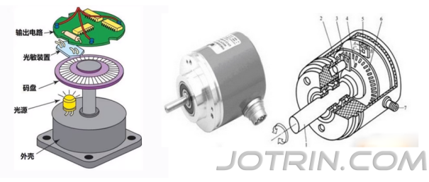
photoelectric encoder is a sensor that converts the mechanical geometric displacement on the output shaft into pulses or digital quantities through photoelectric conversion. This is currently the most widely used sensor. Photoelectric encoders are composed of a light source, an optical code disk and a photosensitive element.
The grating disk is a circular plate with a certain diameter that is divided into several rectangular holes. Since the photoelectric code disk is coaxial with the motor, when the motor rotates, the grating disk rotates at the same speed as the motor. A detection device composed of light-emitting diodes and other electronic components detects and outputs a number of pulse signals. By calculating the number of pulses output by the photoelectric encoder per second, the current speed of the motor can be reflected.
In addition, in order to determine the direction of rotation, the code wheel can also provide two pulse signals with a phase difference of 90°.
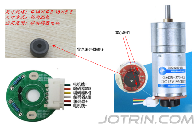
Hall Encoder is a sensor that converts the mechanical geometric displacement on the output shaft into pulses or digital quantities through magnetoelectric conversion.
Hall encoder is composed of Hall code disk (magnetic ring) and Hall element.
Hall code disk is equally arranged with different magnetic poles on a circular plate of a certain diameter. The Hall code disk is coaxial with the motor. When the motor rotates, the Hall element detects and outputs a number of pulse signals. In order to determine the steering direction, it generally outputs two sets of square wave signals with a certain phase difference.
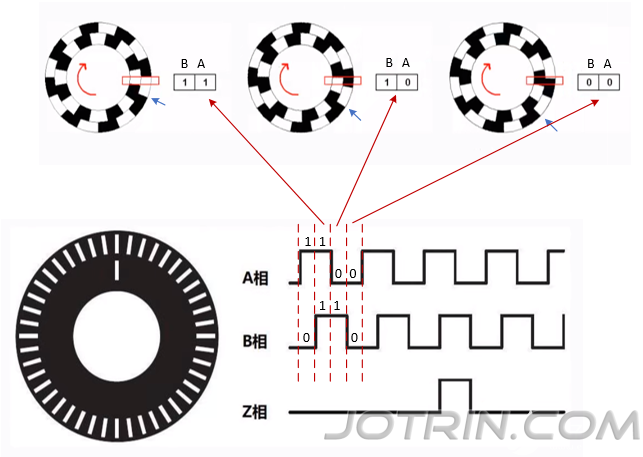
incremental encoder converts the displacement information when the equipment is moving into a continuous pulse signal. The number of pulses represents the amount of displacement. Its characteristics are as follows: The pulse waveform output by the
The signal is output only when the device is in motion.
generally outputs two sets of signals, channel A and channel B, and has 90° The phase difference (1/4 period), collecting these two sets of signals at the same time can calculate the movement speed and direction of the device.
As shown in the figure below, the signals of channel A and channel B have the same period, and the phase difference is 1/4 cycle. Combining the signal values of the two phases:
When phase B and A phase both read a high level (1 1), then B reads a high level, and A reads a low level (1 0), it is a clockwise rotation
When phase B and phase A first read a low level (0 0), then B reads a high level, and A reads a low level (1 0), it is a counterclockwise rotation
In addition to channel A and channel B, an additional channel Z signal will be set to represent the encoder-specific reference position
As shown below, after the sensor rotates once, Z Only the axis signal will output a pulse. When the Z axis is output, the absolute position of the code disk can be calculated by clearing the count of the AB channel.
The incremental encoder only outputs the position change and movement direction of the device, and does not output the absolute position of the device.
The overall structure of the absolute encoder is similar to the incremental encoder. They are both composed of a code disk, a detection device and an amplification and shaping circuit. However, the specific code disk structure and the meaning of the output signal are different. The code disc of the
It converts the displacement information when the device is moving into a digital quantity through binary encoding (special code disk) and outputs it directly. Its features are as follows:
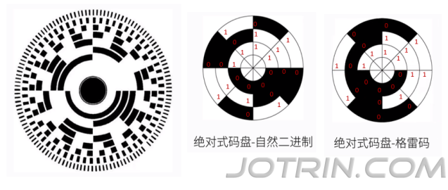
Its code plate uses a number of light-transmitting and opaque wire troughs to form a set of binary codes. These binary codes uniquely correspond to each different angle of the encoder shaft.
absolute encoder has many circles of wire slots, called code tracks. The number and length of the internal wire slots in each (circle) code track are different. Together they form a set of binary codes. One (circle) code track corresponds to one bit of the binary number (usually the outermost code track of the code wheel represents the lowest bit, and the innermost code track represents the highest bit).
code channels determines the number of binary encoding digits. An absolute encoder has N bar code channels, so the total number of binary numbers it outputs is 2 to the Nth power.
can know the absolute position of the device by reading these binary codes, so it is called an absolute encoder.
encoding method generally adopts natural binary, Gray code or BCD code, etc.
The natural binary code wheel is easy to understand, but when there are errors in the manufacturing process of the code wheel, in the critical area of the two sets of signals, the values of all code channels may not change at the same time, or because there is a slight time difference in all sensor detections, wrong values are read. For example, if you span from 000 to 111, theoretically it should read 111. However, if the three barcode tracks from the inside to the outside are not completely aligned, you may read 001 or other outliers. The
Gray code (two adjacent binary numbers are only different by 1 bit) code disk can avoid abnormal data reading of the binary code disk, because the two adjacent signal groups of the Gray code disk will only change by 1 bit. Even if there are errors in the manufacturing process that cause deviations in signal reading, at most there will only be 1 deviation (deviation of adjacent signals).
refers to the smallest unit that the encoder can resolve.
For incremental encoders, the resolution is expressed as the number of pulses generated by one revolution of the encoder shaft, that is, the number of pulses/revolution (Pulse Per Revolution or PPR).
code disk is actually equal to the resolution, also called the number of lines. The more common ones are 5-6000 lines.
For an absolute encoder, the number of digits used by the internal code disk is its resolution, and the unit is bit (bit). Specifically, it is divided into single-turn resolution and multi-turn resolution.
First of all, let’s be clear, accuracy and resolution are two different concepts.
Accuracy refers to the maximum error between each reading of the encoder and the actual position of the rotating shaft, usually expressed in angles, arc minutes or arc seconds. The accuracy of
For example, some absolute encoder parameter tables will write ±20'', which means that there is an error of plus or minus 20 arc seconds between the encoder output reading and the actual position of the rotating shaft.
is determined by various factors such as the machining accuracy of the code plate's engraved lines, the concentricity of the rotating shaft, the temperature characteristics of the material, and the response time of the circuit.
refers to the number of pulses output by the encoder per second, the unit is Hz. The calculation formula is:
Maximum response frequency = resolution * shaft speed / 60
For example, the resolution of a motor's encoder is 100 (that is, there are 100 grids in one photoelectric code disk), and the shaft speed is 120 revolutions per minute (that is, 2 revolutions per second), then the response frequency is 100*120/60=200Hz, that is, at this speed, the encoder outputs 200 pulses per second (the motor drives the encoder to rotate 2 times).
For incremental encoders, the signals of each channel are output independently. The output circuit forms usually include open-collector output, push-pull output, differential output, etc.
For absolute encoders, since they directly output dozens of binary numbers, in order to ensure the transmission rate and signal quality, serial output or bus-type output is generally used, such as synchronous serial interface (SSI), RS485, CANopen or EtherCAT, etc. Some are also parallel output, and the output circuit form is the same as that of the incremental encoder.
What does encoder frequency multiplication mean? For example, a grating encoder has N grids in one circle. In theory, the motor drives the encoder to rotate once, and can only output N signals. Through frequency multiplication technology, it can achieve one revolution, but can output N*n signals, where n is the frequency multiplier number.
incremental encoder is generally a square wave with a duty cycle of 50%, and the phase difference between channels A and B is 90°.
If only channel A is used for counting, and only the rising edge of channel A is captured, the count value of one revolution = the number of grids on the code wheel, which is 1 multiplication (no frequency multiplication)
If only channel A is used for counting, and the rising edge and falling edge of channel A are captured, the count value of the encoder for one revolution is doubled, achieving 2 times the frequency
If both channel A and channel B are used to count, and both rising and falling edges are captured, a 4x frequency multiplication is achieved.
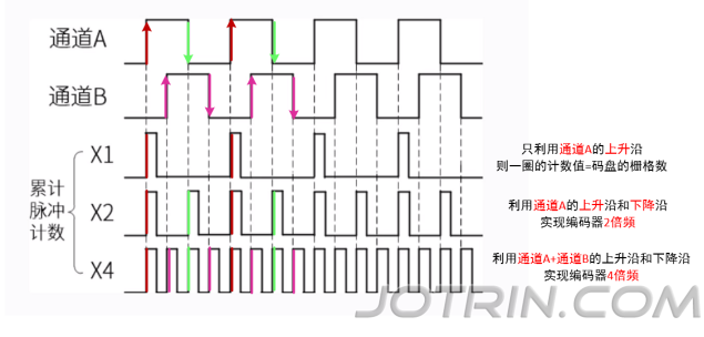
Assume that the resolution of an incremental encoder is 600PPR, and the minimum angle that can be resolved is 0.6°. Doubling it by 4 is equivalent to increasing the resolution to 600*4=2400PPR. At this time, the minimum angle that the encoder can resolve is 0.15°.
is also called frequency measurement method. This method is to count the number of encoder pulses during a fixed period of time (in seconds) and calculate the speed value. The M method is suitable for measuring high speeds.
Assumption:
The total number of pulses in a single circle of the encoder is C (constant)
statistical time is (fixed value, unit second)
The number of encoder pulses counted during this time is (measurement value)
Then: the calculation formula of speed n (revolutions/second) is:
How to understand this formula:
/C means how many encoder pulses there are in the statistical time, and then divided by the statistical time, that is, how many turns in 1s (unit time)
For example: the statistical time is 3s, the number of pulses measured within 3s is 60, and the encoder’s single-turn pulse number C is 20, then the speed circle per second
Since C is a constant, the speed n is proportional to. This makes:
At high speed, the measurement becomes larger, which can obtain better measurement accuracy and stability.
But at low speeds (low to each (there are only a few pulses in it), the calculated speed error at this time will be relatively large and very unstable.
As shown in the figure below, the square wave is the pulse output by a certain channel of the encoder.
When the rotational speed is high, the count value in each statistical time is larger, and a more accurate rotational speed measurement value can be obtained.
When the speed is low, each statistical time The count value within is smaller. Since the starting position of the statistical time does not necessarily correspond to the rising edge of the encoder pulse, when the starting position of the statistical time is different, there will be an error of one pulse (when only counting rising edges, there will be a maximum of 1 pulse error, when counting rising edges and falling edges, there will be a maximum of 2 pulse errors).
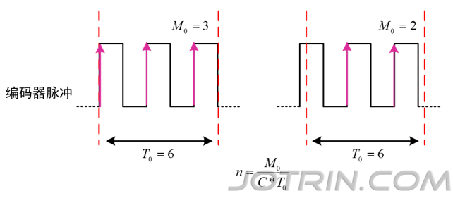
can improve the accuracy of M method in low-speed measurement by increasing the number of pulses measured per unit time by frequency doubling (for example, the original captured pulses are only 4, and after 4 times the frequency, the same motor status becomes 16), but it cannot fundamentally change the measurement problem at low speed.
is also called the period measurement method. This method is to create a high-frequency pulse of a known frequency and count them. The T method is suitable for measuring low speeds.
Assumption:
The total number of pulses in a single circle of the encoder is C (constant)
The frequency of high-frequency pulse is (fixed value, unit Hz)
captures the interval between two adjacent pulses of the encoder as , and the count value between them is (measurement value)
Then: the calculation formula of speed n is:
How to understand this formula:
1/ That is, how many encoder pulses there are in 1s, divided by the number of pulses in one revolution C, that is, how many revolutions are made in 1s
/ That is, the number of high-frequency pulses in 1s divided by the number of high-frequency pulses between two encoder pulses, that is, how many encoder pulses there are in 1s, and then divided by the number of pulses in one circle C, that is, how many turns in 1s
For example: the period of the high-frequency pulse is 1ms, that is, the frequency is 1000Hz. Between the two pulses of the encoder, the number of high-frequency pulses generated is 50 (that is, the interval between two encoder pulses is 0.05s). The number of pulses C in one revolution of the encoder is 20, and the speed is one revolution per second.
. This makes:
At high speed, the encoder pulse interval time is very small, so that the high-frequency pulse count value in the measurement period also becomes very small, resulting in larger measurement errors.
is large enough at low speeds and there are enough in the measurement period, so the T method is just the opposite of the M method and is more suitable for measuring low speeds.
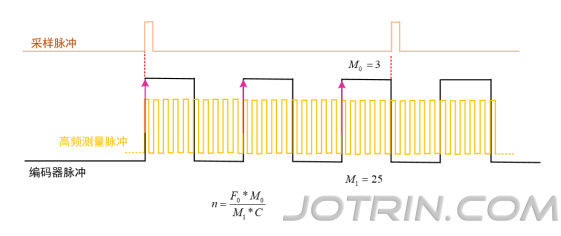
As shown in the figure below, the black square wave is the pulse output by a certain channel of the encoder, and the yellow square wave is the high-frequency measurement pulse.
When the rotational speed is low, the number of high-frequency measurement pulses is larger, and a more accurate rotational speed measurement value can be obtained.
When the speed is high, the time interval between the two pulses of the encoder becomes shorter, resulting in a smaller number of high-frequency measurement pulses. Since the rising edge position of the high-frequency pulse does not necessarily correspond to the rising edge of the encoder pulse, when the rising edge positions of the two waves are different, there will be a pulse error.

This method combines the respective advantages of the M method and the T method, measuring both the number of encoder pulses and the number of high-frequency pulses within a certain period of time.
In a relatively fixed time, assuming:
The number of encoder pulses generated (measured value)
counts a high-frequency pulse with a known frequency (fixed value, unit Hz), the count value is (measured value), and the speed value is calculated
encoder is C (constant). The number of transparent line grooves on the
then speed n The calculation formula is:
For example: in a relatively fixed period of time, the number of encoder pulses is 3; the period of high-frequency pulses is 1ms, that is, the frequency is 1000Hz, and the number of high-frequency pulses generated is 150; the number of pulses C in one revolution of the encoder is 20, and the rotation speed is one revolution per second.
Since and C in the M/T method formula are constants, the rotation speed n is only affected by and .
At high speed, increase and decrease, equivalent to M method
At low speed, increases and decreases, which is equivalent to the T method.