-
Customer Service QQ
3297421414
-
Phone
Monday to Saturday 9:30 - 22:00
Phone : 18682486380
18126541905 -
Official WeChat
 Scan the official WeChat QR code for an instant quote
Jiechi Electronics Co., Ltd.
100% quality | A global multi-service platform for electronic components
Customer Service QQ
3297421414
Phone
Monday to Saturday 9:30 - 22:00
Phone : 18682486380
18126541905
Official WeChat
Scan the official WeChat QR code for an instant quote2021-08-13 Views:6
The main pollutants in indoor air include total volatile organic compounds (Total Volatile Organic Compound, TVOC), carbon dioxide (CO2) and dust particles with a maximum diameter of 2.5 Micron particulate matter (PM2.5), etc. Two other parameters affect indoor air quality: the humidity and temperature levels of the indoor environment. An indoor air quality monitor (Air Quality Monitor, AQM) is a real-time monitoring system that measures the values of the above pollutants and parameters. The smart and secure AQM is capable of transmitting monitored air quality parameters to cloud servers via wireless communication for real-time data modeling, real-time pollution data mapping, smart notifications, and generation of automated reports.
In this solution, the AQM system is designed and implemented using the core-independent peripherals (CoreIndependent Peripheral, CIP) and intelligent analog peripherals in the 8-bit AVR® processor ATmega4808 microcontroller (AVR MCU). Microchip’s CryptoAuthentication™ secure element (ATECC608A) and fully certified Wi-Fi® module (ATWINC1510) are used to securely connect smart AQM to the Google Cloud™ IoT Core platform.
2. Overview of Microchip indoor air quality monitoring solution
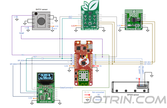
This solution will be implemented using the AVR-IoT WG development board. The AVR-IoT development board uses Microchip's ATmega4808 microcontroller, CryptoAuthentication secure element (ATEC608A) and Wi-Fi module (ATWINC1510). The AQM system also uses click boards from Mikroelektronika (which houses the sensors), EEPROM and OLED displays, but does not include humidity and particulate matter (PM) sensors. PM sensors and humidity sensors are connected using PROTO click. AQM uses a Microchip sandbox account registered on the Google Cloud IoT Core platform. The AVR-IoT WG development board is pre-configured to communicate with this account. A web application (i.e. web page) designed specifically for the AVR-IoT WG development board can visualize data as graphics.
After powering on, AQM will search for a preconfigured Wi-Fi router to connect to. If you have a Wi-Fi router, AQM will connect to it and access the Internet. If there is no Wi-Fi router, it will continuously search and light up a red LED to indicate a Wi-Fi connection error. The microcontroller will monitor indoor ambient temperature and humidity as well as major airborne pollutants such as PM2.5, CO2 and TVOC. These readings taken will also be processed and the AQI value calculated based on the PM2.5 sensor readings. AQI and other acquired air quality parameters are stored in an external EEPROM and displayed on the OLED. If AQM finds an internet connection, it uploads the AQI and other parameters to Google Cloud. Thereafter, the microcontroller enters standby sleep mode and wakes up periodically to monitor the sensors and transmit the processed data to the cloud. Additionally, the microcontroller can instantly wake up from sleep in response to a switch press event and display air quality parameters on the OLED. Figure 1-1 shows the entire AQM system including cloud and web pages.
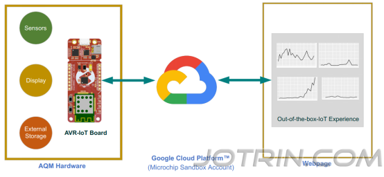
Figure 1: Entire AQM system including cloud and web page
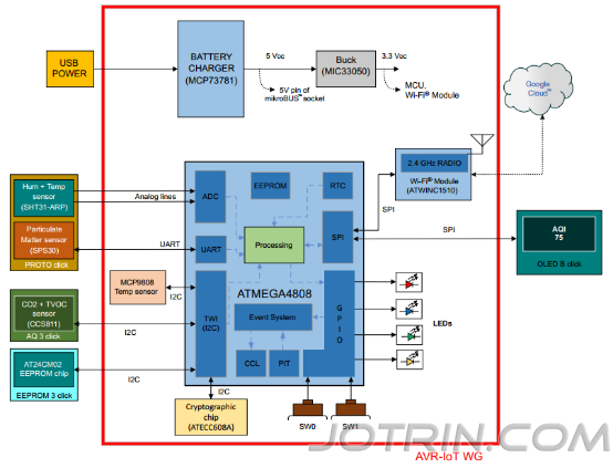
microcontroller and Google Cloud is protected by the secure element ATECC608A on the AVR-IoT WG development board. Users can view all air quality parameters through the web page. This page fetches data from Google Cloud every second and updates a map of air quality parameters.
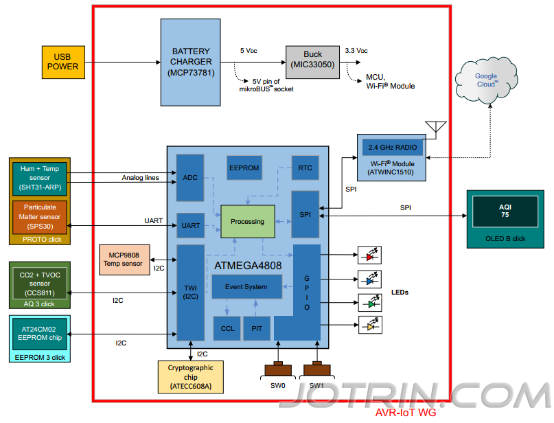
Figure 2: AQM system block diagram
The AQM system based on the Microchip solution has the following functions:
• Microchip megaAVR® microcontroller – ATmega4808 with CIP and smart analog peripherals
• PM2.5, CO2, TVOC, humidity and temperature monitoring
• Hardware security: CryptoAuthentication secure element ATECC608A
• Wireless connectivity: fully certified Wi-Fi module ATWINC1510
• Google Cloud Connectivity
• OLED display
• Data logging
3. Solution hardware overview
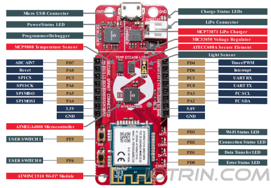
AQM hardware is shown in the figure below: The peripherals of ATmega4808 used in the
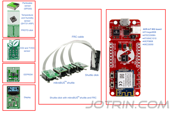
Figure 3: AQM hardware
AVR-IoT WG development board combines the powerful 8-bit ATmega4808 microcontroller, ATECC608A and ATWINC1510 to connect embedded applications to the Google Cloud IoT Core platform in the simplest and most efficient way. The development board includes an on-board debugger that allows programming and debugging of the microcontroller without the need for external hardware.
MCU-ATmega4808
ATmega4808 is a microcontroller with an 8-bit AVR processor running at speeds up to 20 MHz and equipped with 48 KB of flash memory, 6 KB of SRAM and 256 bytes of EEPROM. The microcontroller uses the latest low-power CIP including event system, smart analog peripherals and advanced peripherals.
AQM system include:
l Analog-to-Digital Converter (ADC)
l Universal Synchronous and Asynchronous Receiver and Transmitter (USART)
l Serial Peripheral Interface (SPI)
l Dual-mode master/slave dual-wire interface (Two-Wire Interface, TWI): I2C compatible
l Real-time counter (RTC)
l Periodic Interrupt Timer (PIT)
l Sleep controller
l EEPROM data memory
l Event system
l Configurable custom logic (CCL)
safety element - ATECC608A
ATECC608A Employs ultra-secure hardware-based encryption key storage and encryption countermeasures, eliminating potential backdoors associated with software vulnerabilities. ATECC608A is used to store private and public keys required for secure IoT communications. The ATECC608A communicates with the host controller via an I2C interface.
Wireless connection - ATWINC1510 Wi-Fi® module
ATWINC1510 is an IEEE 802.11 b/g/n IoT network controller. The ATWINC1510 Wi-Fi module integrates the ATWINC1510 SoC, 26MHz oscillator, impedance matching circuitry and printed antenna or microcoaxial (µFL) connector for external antenna. The module communicates with the host controller via the SPI interface. The
digital temperature sensor——MCP9808
The MCP9808 digital temperature sensor provides a wide range of applications with 0.5°C accuracy (-20°C to +100°C) and 12-bit high temperature resolution. Other features include shutdown, under/over temperature monitors, and critical temperature alarms. The digital sensor is connected to the microcontroller via an I2C interface. ANPEC for
Buck regulator - MIC33050
MIC33050 is a high-efficiency 600 mA PWM synchronous buck regulator with internal inductor. Its key features include an input voltage range of 2.7V to 5.5V, an output current of 600 mA, a quiescent current of 20 µA, and low output voltage ripple. The WRB1205MD-6W part manufactured by
4. Solution Firmware Overview
AQM application firmware is developed based on the AVR-IoT protocol stack; for more details about the AVR-IoT protocol stack, please refer to the AVR-IoT WG development board and its documentation. Figure 4 shows the AVR-IoT protocol stack and application firmware modules. The
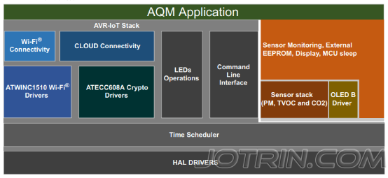
Figure 4: Application firmware layer
AQM application code
application firmware periodically acquires data from the sensor and processes it. It calculates the AQI and sends the processed data to Google Cloud. In addition, the processed data is displayed on the OLED display and stored in an external EEPROM for recording. Figure 5 gives an overview of the application flowchart. In response to market development needs,
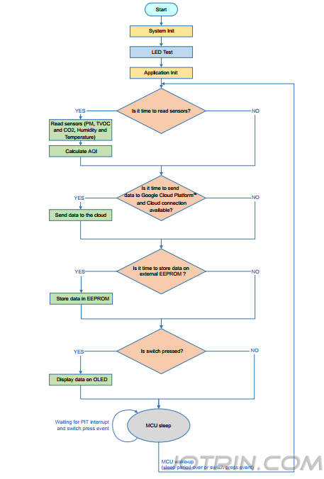
Figure 5: Application flow chart
5. Development environment
software tool
can use Atmel Studio or MPLAB X IDE for firmware development.
Development with Atmel Studio includes:
l Atmel Studio 7
l AVR GCC compiler
l Atmel START configurator tool
Developing with MPLAB X IDE includes:
l MPLAB X IDE
l AVR GCC compiler
l MPLAB code configurator (MCC)
Firmware configuration and generation
Application firmware can be generated using Atmel START or MCC. For more details on the process of generating firmware using the Atmel START or MCC framework, see AN3417 - Indoor Air Quality Monitor: Firmware Creation Using Atmel START and MPLAB® Code Configurator (MCC). The
Microcontroller Programming
To program the application firmware on the microcontroller, see the AVR-IoT WG Development Board User Guide.
6. Conclusion
This article describes the details of implementing the AQM solution using the AVR-IoT WG development board (ATmega4808). Embedded designs can be protected using the ATECC608A CryptoAuthentication™ secure element, which handles authentication for each device. Wireless connectivity can be seamlessly added using the Wi-Fi module (ATWINC1510)
► display version photo
► solution block diagram
► Principle Block Diagram
► Core technology advantages
• Microchip ATmega4808 microcontroller with CIP and smart analog peripherals
• Enables PM2.5, CO2, TVOC, humidity and temperature monitoring
• Enables hardware security: CryptoAuthentication Secure Element ATECC608A
• Enables wireless connectivity: fully certified Wi-Fi module ATWINC1510
• Secure connection to Google Cloud
• With OLED display
• Enables data logging
► Solution specifications
MCU-ATmega4808
ATmega4808 is a microcontroller with an 8-bit AVR processor running at speeds up to 20 MHz and equipped with 48 KB of flash memory, 6 KB of SRAM and 256 bytes of EEPROM. The microcontroller uses the latest low-power CIP including event system, smart analog peripherals and advanced peripherals.
safety element - ATECC608A
ATECC608A Employs ultra-secure hardware-based encryption key storage and encryption countermeasures, eliminating potential backdoors associated with software vulnerabilities. ATECC608A is used to store private and public keys required for secure IoT communications. The ATECC608A communicates with the host controller via an I2C interface.
Wireless connection - ATWINC1510 Wi-Fi® module
ATWINC1510 is an IEEE 802.11 b/g/n IoT network controller. The ATWINC1510 Wi-Fi module integrates the ATWINC1510 SoC, 26MHz oscillator, impedance matching circuitry and printed antenna or microcoaxial (µFL) connector for external antenna. The module communicates with the host controller via the SPI interface.
digital temperature sensor——MCP9808
The MCP9808 digital temperature sensor provides a wide range of applications with 0.5°C accuracy (-20°C to +100°C) and 12-bit high temperature resolution. Other features include shutdown, under/over temperature monitors, and critical temperature alarms. The digital sensor is connected to the microcontroller via an I2C interface. ANPEC for
Buck regulator - MIC33050
MIC33050 is a high-efficiency 600 mA PWM synchronous buck regulator with internal inductor. Its key features include an input voltage range of 2.7V to 5.5V, an output current of 600 mA, a quiescent current of 20 µA, and low output voltage ripple. The WRB1205MD-6W part manufactured by